There is plenty to think about when planning for the introduction of VTOL (vertical take-off and landing) operations at current (helipad/heliport) and future (composite helipad/heliport/vertiport) facilities, particularly as the technology progresses from testing/evaluation to operational, and different jurisdictions produce standards and guidance for vertiport design and operation.
The Federal Aviation Administration (FAA) has just released draft Engineering Brief No 105, Vertiport Design, for consideration and comment by industry.
The Engineering Brief specifies design guidance for vertiports (used for longer term take-off and landing, and access to aircraft facilities) and vertistops (used only for quick stops), including modification of existing helicopter and aeroplane landing facilities and the establishment of new sites. Although the design guidance contained refers to vertiport design, the design guidance applies to both vertiports and vertistops.
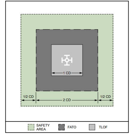
This blog sets out some of the more significant points of interest, including the obviously different markings shown in the accompanying image extracted from the Design Brief.
Definitions
Controlling Dimension (CD): The CD is the longest distance between the two outermost opposite points on the design VTOL aircraft (e.g., wingtip-to-wingtip, rotor tip-to-rotor tip, rotor tip-to-wingtip, fuselage-to-rotor tip), measured on a level horizontal plane that includes all adjustable components extended to their maximum outboard deflection.
Vertiport: An area of land or a structure, used or intended to be used, for electric, hydrogen, and hybrid VTOL landings and take-offs and includes associated buildings and facilities.
Vertistop: An area similar to a vertiport, except that no charging, fueling, defueling, maintenance, repairs, or storage of aircraft are permitted.
Composite Aircraft
The vertiport design guidance relies on design characteristics, expected performance capabilities, and preliminary assumptions regarding landing area design, until there is adequate research on these emerging aircraft to develop a performance based vertiport design advisory circular.
The Composite Aircraft is electric battery driven, weighs ≤3175 kg, is ≤15.2 m wide and long, has a pilot on board, and is operated in visual meteorological conditions (day and night).
Spatial requirements
An important difference to current helicopter landing site/heliport design is the significantly larger load bearing area required for the touchdown and lift off (TLOF) and final approach and take-off (FATO) areas, which, after adding the 1/2CD safety area around the FATO, means the vertiport needs a lot more space.
For vertiports, the TLOF area is measured by multiplying the aircraft CD by 1, while the load bearing FATO is measured by multiplying the aircraft CD by 2. An overall safety area of 3 x CD is required.
According to ICAO Annex 14 Vol II Heliport Design, a helicopter with a D-value (D) of 15.2 m requires an obstacle clear safety area of 2xD (30.4 m), whereas a VTOL with the maximum 15.2 m CD of the Composite Aircraft requires 45.6 m clear of obstacles.
For reference, the AW139 commonly operated by aeromedical and rescue services has a D-value of 16.65 and a rotor diameter of 13.8 m. This would require an obstacle clear safety area of 33.3 m.
In summary, current helipads/heliports and their associated operational airspace may not be suitable for VTOL aircraft without significant re-design, and new facilities will need to be future-proofed to accommodate a range of requirements that are still in the very early stages of development.
To find out more about Aviation Projects’ vertiport planning capability, contact us.
The draft Engineering Brief can be downloaded via the following link:
Tags: Vertiport, Vertistop, Advanced Air Mobility, VTOL, EVTOL, Airport Master Planning, Helipad